Recycling old video game controllers
In this post I will show you how to use a USB capable AVR MCU such as the atmega 32u4 and the LUFA framework in order to create USB joystick and joypad HID adapters.
LUFA
LUFA is a USB stack targetting USB-capable AVR MCUs. It comes with many demos such as MIDI HID, joystick HID , mass storage, CDC/ACM … Using LUFA, an AVR MCU and your ingenuity, you can implement your own USB devices. Today, I’m going to build some USB joysticks and joypads adapters using an Arduino clone. The board says “Freaduino Micro V1.2” on the PCB but it doesn’t really matter. All we need to know is that it’s 32u4 based and quite similar to an official Arduino Micro board. I got that one from dealextreme for 23US$.
Since it’s going to deal a little bit with low level USB details, I recommend having a look at USB in a nutshell whenever I’m unclear or skeeping too many details.
Let’s get started
As a starting point, we will modify the LUFA joystick demo found in Demos/Device/ClassDriver/Joystick so that it builds with the Arduino toolchain. LUFA is written in C99 and heavily uses designated initializer in order to define USB descriptors whereas the Arduino framework is a mix of C and C++. Since mixing C++ and C99 source code is a pain, I will only consume the C APIs from the Arduino framework whenever needed.
LUFA comes with its own build system which relies on avr-gcc. I will be using the avr-gcc distribution shipped with the Arduino framework. I set my PATH accordingly with something like that:
export PATH=$HOME/arduino-1.5.5/hardware/tools/avr/bin:$PATHFirst thing is to make a copy of the joystick demo folder and edit the makefile. Luckily LUFA has some support for the Arduino Leonardo through the preprocessor symbol BOARD_LEONARDO.
Leonardo is 32u4 based too but its pin mapping between “AVR world” and “Arduino world” is slightly different from the Micro: be careful as it can be tricky.
Here are the makefile variables which need to be updated:
MCU          = atmega32u4
ARCH         = AVR8
BOARD        = LEONARDO
F_CPU        = 16000000
F_USB        = $(F_CPU)
LUFA_PATH    = /home/sb/Hacking/LUFA/LUFA
make won’t succeed out of the box though:
In file included from Joystick.h:48,
                 from Joystick.c:37:
../../../../LUFA/../LUFA/Drivers/Board/Joystick.h:125:31: error: Board/Joystick.h: No such file or directory
In file included from Joystick.h:50,
                 from Joystick.c:37:
../../../../LUFA/../LUFA/Drivers/Board/Buttons.h:163:30: error: Board/Buttons.h: No such file or directory
Joystick.c: In function ‘SetupHardware’:
Joystick.c:103: warning: implicit declaration of function ‘Joystick_Init’
Joystick.c:105: warning: implicit declaration of function ‘Buttons_Init’
Joystick.c: In function ‘CALLBACK_HID_Device_CreateHIDReport’:
Joystick.c:163: warning: implicit declaration of function ‘Joystick_GetStatus’
Joystick.c:164: warning: implicit declaration of function ‘Buttons_GetStatus’
Joystick.c:166: error: ‘JOY_UP’ undeclared (first use in this function)
Joystick.c:166: error: (Each undeclared identifier is reported only once
Joystick.c:166: error: for each function it appears in.)
Joystick.c:168: error: ‘JOY_DOWN’ undeclared (first use in this function)
Joystick.c:171: error: ‘JOY_LEFT’ undeclared (first use in this function)
Joystick.c:173: error: ‘JOY_RIGHT’ undeclared (first use in this function)
Joystick.c:176: error: ‘JOY_PRESS’ undeclared (first use in this function)
Joystick.c:179: error: ‘BUTTONS_BUTTON1’ undeclared (first use in this function)
make: *** [Joystick.o] Error 1
The reason is that the joystick demo assumes that the targeted hardware do have a joystick and some buttons you can access through the stuff
in Buttons.h and Joystick.h. This won’t be the case for that board and we simply should neither include LUFA/Drivers/Board/Joystick.h and LUFA/Drivers/Board/Buttons.h nor reference any JOY_* variable. Instead we’re going to write our own code to probe the real controllers.
Here is a cleaned up and building version of the joystick demo. It does nothing special except describing itself as a USB joystick HID. Here is what happens when I plug the provisioned MCU to my computer:
$ dmesg
[24622.916180] usb 2-1: new full-speed USB device number 5 using uhci_hcd
[24623.097587] usb 2-1: New USB device found, idVendor=03eb, idProduct=2043
[24623.097603] usb 2-1: New USB device strings: Mfr=1, Product=2, SerialNumber=0
[24623.097614] usb 2-1: Product: LUFA Joystick Demo
[24623.097623] usb 2-1: Manufacturer: Dean Camera
[24623.105948] input: Dean Camera LUFA Joystick Demo as /devices/pci0000:00/0000:00:1d.0/usb2/2-1/2-1:1.0/input/input14
[24623.106779] hid-generic 0003:03EB:2043.0004: input,hidraw0: USB HID v1.11 Joystick [Dean Camera LUFA Joystick Demo] on usb-0000:00:1d.0-1/input0

$ lsusb
Bus 002 Device 005: ID 03eb:2043 Atmel Corp. LUFA Joystick Demo Application

$ jstest /dev/input/js0
Driver version is 2.1.0.
Joystick (Dean Camera LUFA Joystick Demo) has 3 axes (X, Y, Z)
and 2 buttons (Trigger, ThumbBtn).
Testing ... (interrupt to exit)
Axes:  0:     0  1:     0  2:     0 Buttons:  0:off  1:off
The workflow
Here is the workflow to implement a controller:
- create and send an HID report descriptor for the controller: number of axis, buttons, their range and resolution;
- create HID reports of the controller state whenever it’s being probed by the USB host.
Level 1: Pete’s arcade stick
Let’s start with something easy. This is Pete’s heavy duty arcade stick. It’s massive. It’s obviously a 2 axis stick and uses 4 momentary microswitches: that’s enough to play PacMan.
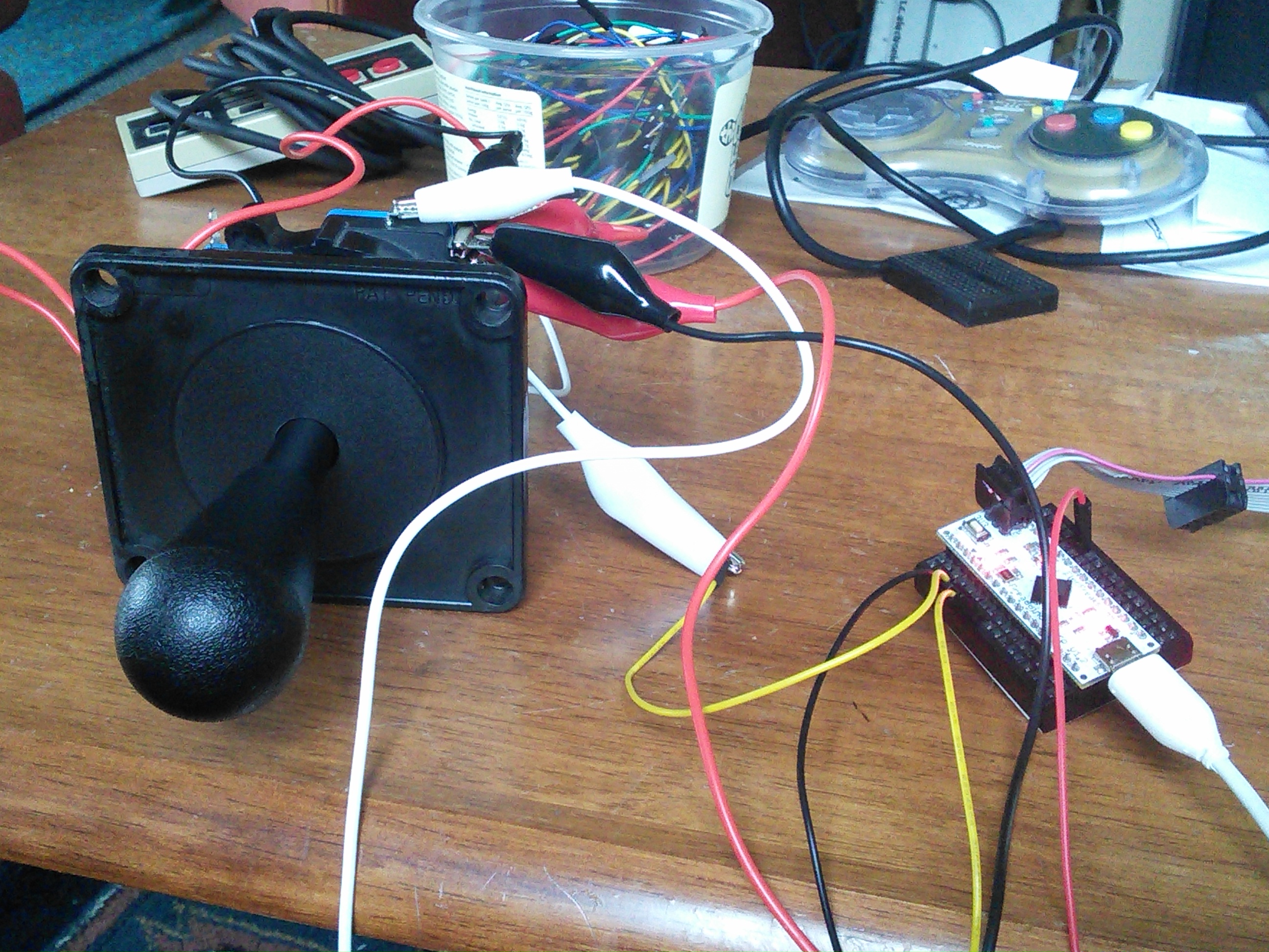
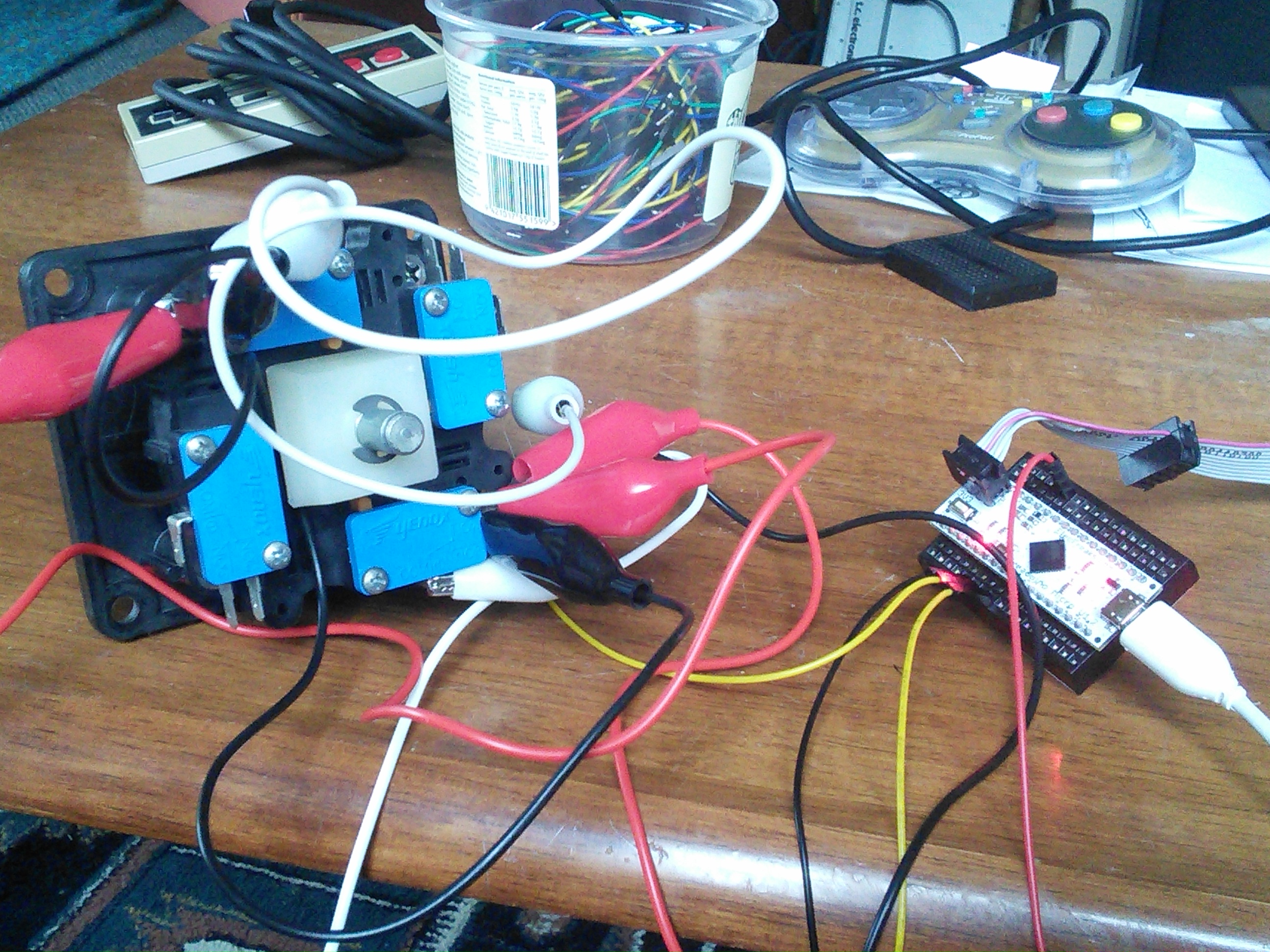
The firmware code for this stick can be found here
Descriptor
A descriptor is a binary string describing device capabilities that the USB host uses to decode the state of that device. Writing a valid descriptor from scratch is a pain and if you’re a beginner like me, I suggest you start modifying a valid joystick descriptor.
Using LUFA macros
LUFA defines a set of macros to create HID descriptors. Here is one for the joystick using LUFA stuff:
#define HID_RI_USAGE_JOYSTICK HID_RI_USAGE(8, 0x04)
#define HID_RI_USAGE_X HID_RI_USAGE(8, 0x30)
#define HID_RI_USAGE_Y HID_RI_USAGE(8, 0x31)
#define HID_DESCRIPTOR_PETE_JOYSTICK \
    HID_RI_USAGE_PAGE(8, 0x01),                 \
    HID_RI_USAGE_JOYSTICK,                      \
    HID_RI_COLLECTION(8, 0x00),                 \
            HID_RI_USAGE_X,                     \
            HID_RI_USAGE_Y,                     \
            HID_RI_LOGICAL_MINIMUM(16, -1),     \
            HID_RI_LOGICAL_MAXIMUM(16, 1),      \
            HID_RI_PHYSICAL_MINIMUM(16, -1),    \
            HID_RI_PHYSICAL_MAXIMUM(16, 1),     \
            HID_RI_REPORT_COUNT(8, 2),          \
            HID_RI_REPORT_SIZE(8, 8),           \
            HID_RI_INPUT(8, HID_IOF_DATA | HID_IOF_VARIABLE | HID_IOF_ABSOLUTE), \
    HID_RI_END_COLLECTION(0)

const USB_Descriptor_HIDReport_Datatype_t PROGMEM JoystickReport[] =
{
        HID_DESCRIPTOR_PETE_JOYSTICK
};
Using the HID Descriptor tool
Another way to do that is to use the HID Descriptor Tool from the USB Implementers Forum website. It’s a MS windows software but runs ok under wine.

You can then export the descriptor to a C header file and use it in your project:
// Z:\home\sb\Hacking\ArduJoypadsToHID\ArcadeStickToUSBJoystick\joystick.hid.h


char ReportDescriptor[34] = {
    0x05, 0x01,                    // USAGE_PAGE (Generic Desktop)
    0x15, 0x00,                    // LOGICAL_MINIMUM (0)
    0x09, 0x04,                    // USAGE (Joystick)
    0xa1, 0x01,                    // COLLECTION (Application)
    0x05, 0x01,                    //   USAGE_PAGE (Generic Desktop)
    0x09, 0x01,                    //   USAGE (Pointer)
    0xa1, 0x00,                    //   COLLECTION (Physical)
    0x09, 0x30,                    //     USAGE (X)
    0x09, 0x31,                    //     USAGE (Y)
    0x15, 0xff,                    //     LOGICAL_MINIMUM (-1)
    0x25, 0x01,                    //     LOGICAL_MAXIMUM (1)
    0x35, 0xff,                    //     PHYSICAL_MINIMUM (-1)
    0x45, 0x01,                    //     PHYSICAL_MAXIMUM (1)
    0x95, 0x02,                    //     REPORT_COUNT (2)
    0x75, 0x08,                    //     REPORT_SIZE (8)
    0x81, 0x02,                    //     INPUT (Data,Var,Abs)
    0xc0,                          //   END_COLLECTION
    0xc0                           // END_COLLECTION
};
One added value of this tool is that it can validate your descriptor.
Report
The HID report should be structured accordingly to the descriptor, that is 1 byte (since REPORT_SIZE is 8 bits) for each of the two axis:
typedef struct {
	int8_t  X, Y;
} USB_JoystickReport_Data_t;
Here is how we create a report:
#define JOY_UP 2
#define JOY_DOWN  3
#define JOY_LEFT 4
#define JOY_RIGHT 5

bool CALLBACK_HID_Device_CreateHIDReport(USB_ClassInfo_HID_Device_t* const HIDInterfaceInfo,
                                         uint8_t* const ReportID,
                                         const uint8_t ReportType,
                                         void* ReportData,
                                         uint16_t* const ReportSize) {
	USB_JoystickReport_Data_t* JoystickReport = (USB_JoystickReport_Data_t*)ReportData;
	*ReportSize = sizeof(USB_JoystickReport_Data_t);

	JoystickReport->X = ReadAxis(JOY_LEFT, JOY_RIGHT);
	JoystickReport->Y = ReadAxis(JOY_DOWN, JOY_UP);

	return false;
}

char ReadAxis(int negDirPin, int posDirPin) {
	if(digitalRead(negDirPin)) {
 		return -1;
	}
	if(digitalRead(posDirPin)) {
		return 1;
	}
	return 0;
}
Since we use functions from the Arduino framework such as digitalRead, we must update the makefile:
ARDUINO_AVR_LIBS = /home/sb/Hacking/arduino-1.5.5/hardware/arduino/avr
SRC          = $(TARGET).c Descriptors.c $(ARDUINO_AVR_LIBS)/cores/arduino/wiring_digital.c $(LUFA_SRC_USB) $(LUFA_SRC_USBCLASS)
CC_FLAGS     = -DUSE_LUFA_CONFIG_HEADER -IConfig/ -I$(ARDUINO_AVR_LIBS)/cores/arduino\
	-I$(ARDUINO_AVR_LIBS)/variants/leonardo
Test
$ dmesg
[ 9894.915804] input: Pete Massive arcade stick as /devices/pci0000:00/0000:00:1d.0/usb2/2-1/2-1:1.0/input/input36
[ 9894.917119] hid-generic 0003:03EB:2043.001A: input,hidraw0: USB HID v1.11 Joystick [Pete Massive arcade stick] on usb-0000:00:1d.0-1/input0

$ jstest /dev/input/js0
Driver version is 2.1.0.
Joystick (Pete Massive arcade stick) has 2 axes (X, Y)
and 0 buttons ().
Testing ... (interrupt to exit)
Axes:  0:     0  1:     0
Axes:  0:     0  1: 32767
Axes:  0:     0  1:-32767
and it works.
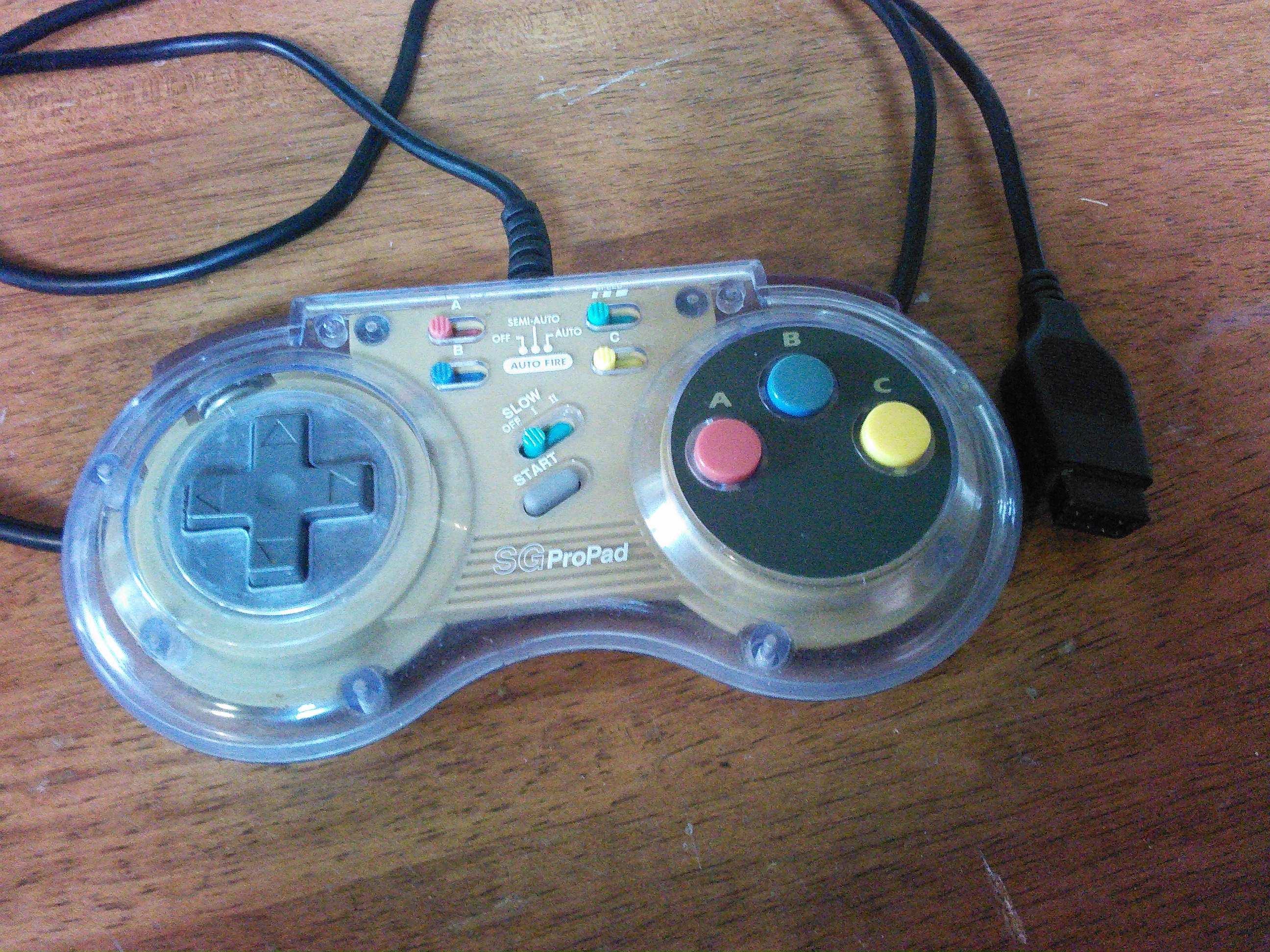
Level 2: Sega Genesis
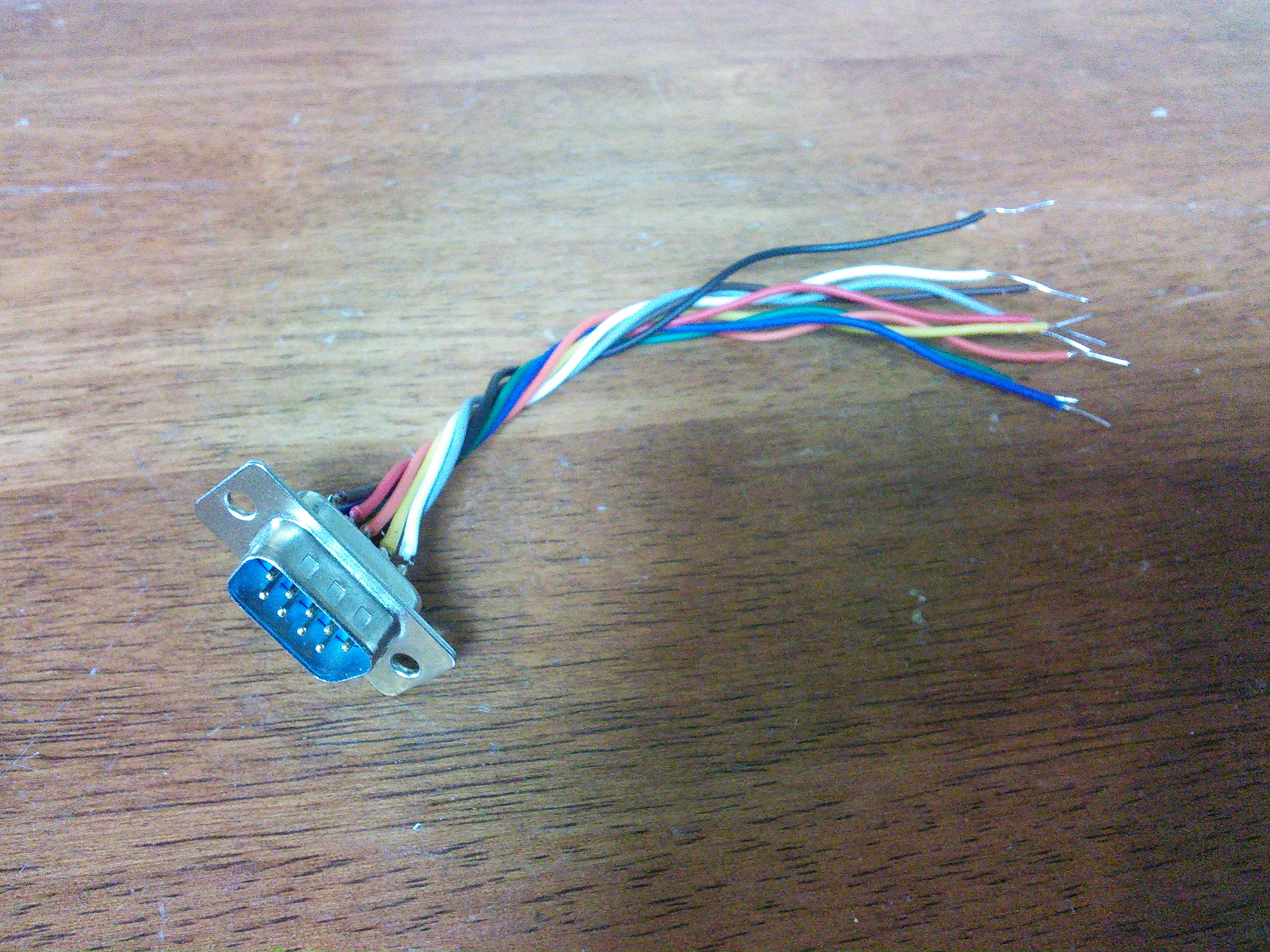
This gamepad features 2 axis, and 4 buttons (labeled A,B,C & Start). It uses a standard DB9 connector which is really handy.

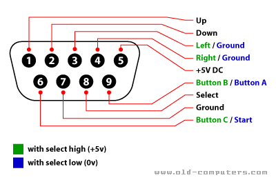
The firmware for this controller can be found here The updated, generated HID descriptor is here and here is how you build a report:
#define SEGA_GENESIS_JOY_UP 2
#define SEGA_GENESIS_JOY_DOWN  3
#define SEGA_GENESIS_JOY_LEFT 4
#define SEGA_GENESIS_JOY_RIGHT 5
#define SEGA_GENESIS_JOY_A 6
#define SEGA_GENESIS_JOY_B 6
#define SEGA_GENESIS_JOY_SELECT 7
#define SEGA_GENESIS_JOY_C 8
#define SEGA_GENESIS_JOY_START  8

bool CALLBACK_HID_Device_CreateHIDReport(USB_ClassInfo_HID_Device_t* const HIDInterfaceInfo,
                                         uint8_t* const ReportID,
                                         const uint8_t ReportType,
                                         void* ReportData,
                                         uint16_t* const ReportSize)
{
  USB_JoystickReport_Data_t* JoystickReport = (USB_JoystickReport_Data_t*)ReportData;
  JoystickReport->Button = 0;

  digitalWrite(SEGA_GENESIS_JOY_SELECT, 1);

  JoystickReport->X = ReadAxis(SEGA_GENESIS_JOY_LEFT, SEGA_GENESIS_JOY_RIGHT);
  JoystickReport->Y = ReadAxis(SEGA_GENESIS_JOY_DOWN, SEGA_GENESIS_JOY_UP);

  if(!digitalRead(SEGA_GENESIS_JOY_B)) {
    bitSet(JoystickReport->Button, 1);
  }

  if(!digitalRead(SEGA_GENESIS_JOY_C)) {
    bitSet(JoystickReport->Button, 2);
  }

  digitalWrite(SEGA_GENESIS_JOY_SELECT, 0);

  if(!digitalRead(SEGA_GENESIS_JOY_A)) {
    bitSet(JoystickReport->Button, 0);
  }

  if(!digitalRead(SEGA_GENESIS_JOY_START)) {
    bitSet(JoystickReport->Button, 3);
  }

  *ReportSize = sizeof(USB_JoystickReport_Data_t);

  return false;
}

char ReadAxis(int negDirPin, int posDirPin) {
  if(!digitalRead(negDirPin)) {
    return -1;
  }
  if(!digitalRead(posDirPin)) {
    return 1;
  }
  return 0;
}
and it works:
$dmesg
[ 4582.479386] input: SEGA Genesis gamepad as /devices/pci0000:00/0000:00:1d.0/usb2/2-1/2-1:1.0/input/input20
[ 4582.480812] hid-generic 0003:03EB:2043.000A: input,hidraw0: USB HID v1.11 Gamepad [SEGA Genesis gamepad] on usb-0000:00:1d.0-1/input0

$ jstest /dev/input/js0
Driver version is 2.1.0.
Joystick (SEGA Genesis gamepad) has 2 axes (X, Y)
and 4 buttons (BtnX, BtnY, BtnZ, BtnTL).
Testing ... (interrupt to exit)
Axes:  0:     0  1:     0 Buttons:  0:on   1:off  2:off  3:off
Level 3: Nintendo NES gamepad
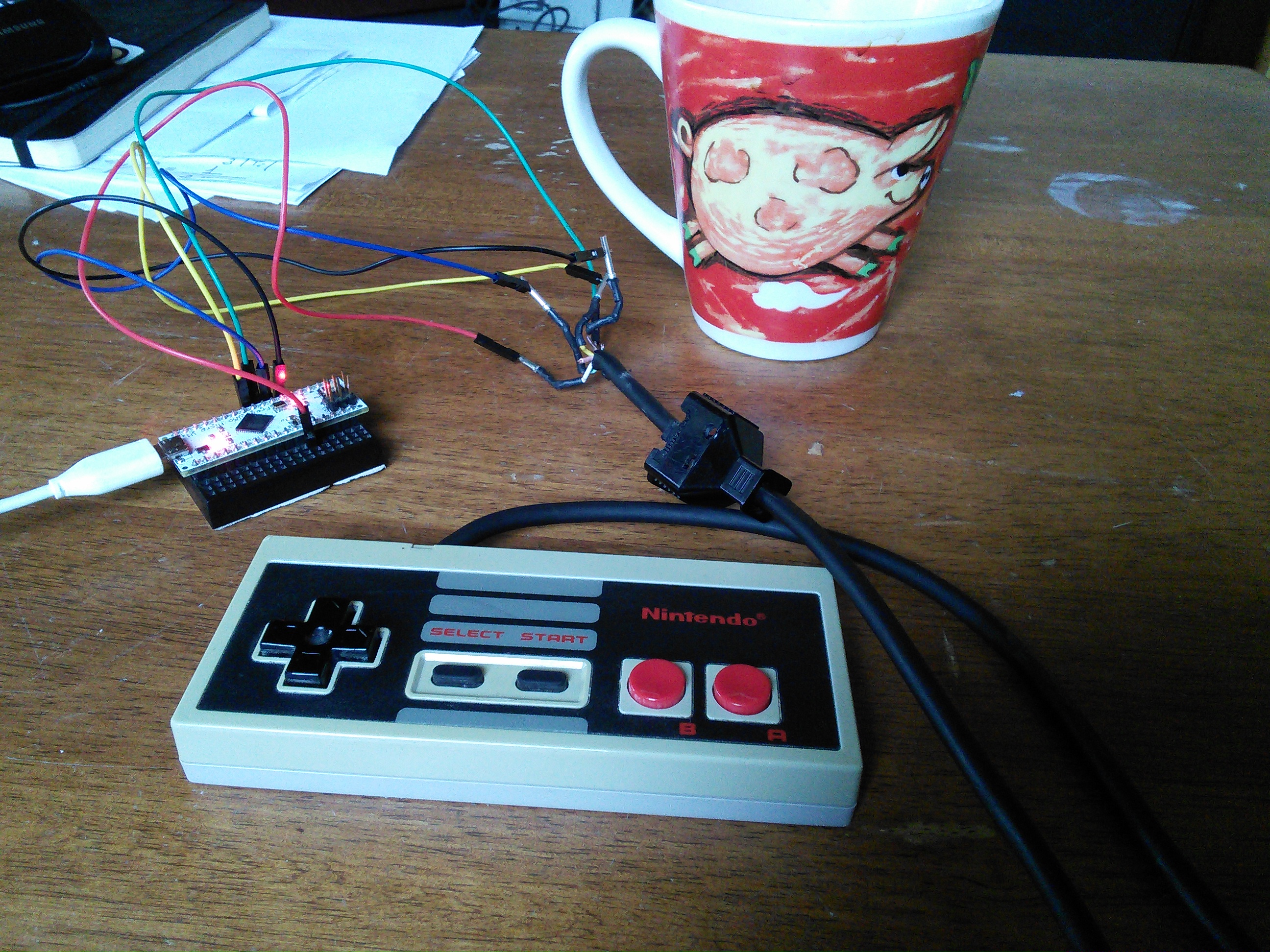
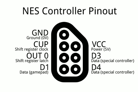
The NES gamepad features 2 axis and 4 buttons (labeled A, B, start & select) just as the Genesis one so that their report descriptors are similar. The NES gamepad uses a shift register to communicate its state: the data, clock and latch pins of the register are accessed via the (non-standard) NES connector. The firmware for the NES gamepad can be found here
$dmesg
[ 5972.096103] usb 2-1: new full-speed USB device number 5 using uhci_hcd
[ 5972.279082] usb 2-1: New USB device found, idVendor=03eb, idProduct=2043
[ 5972.279099] usb 2-1: New USB device strings: Mfr=1, Product=2, SerialNumber=0
[ 5972.279110] usb 2-1: Product: NES gamepad
[ 5972.279119] usb 2-1: Manufacturer: Nintendo
[ 5972.287324] input: Nintendo NES gamepad as /devices/pci0000:00/0000:00:1d.0/usb2/2-1/2-1:1.0/input/input13
[ 5972.288383] hid-generic 0003:03EB:2043.0003: input,hidraw0: USB HID v1.11 Gamepad [Nintendo NES gamepad] on usb-0000:00:1d.0-1/input0
Level 4: The GameCube arcade stick
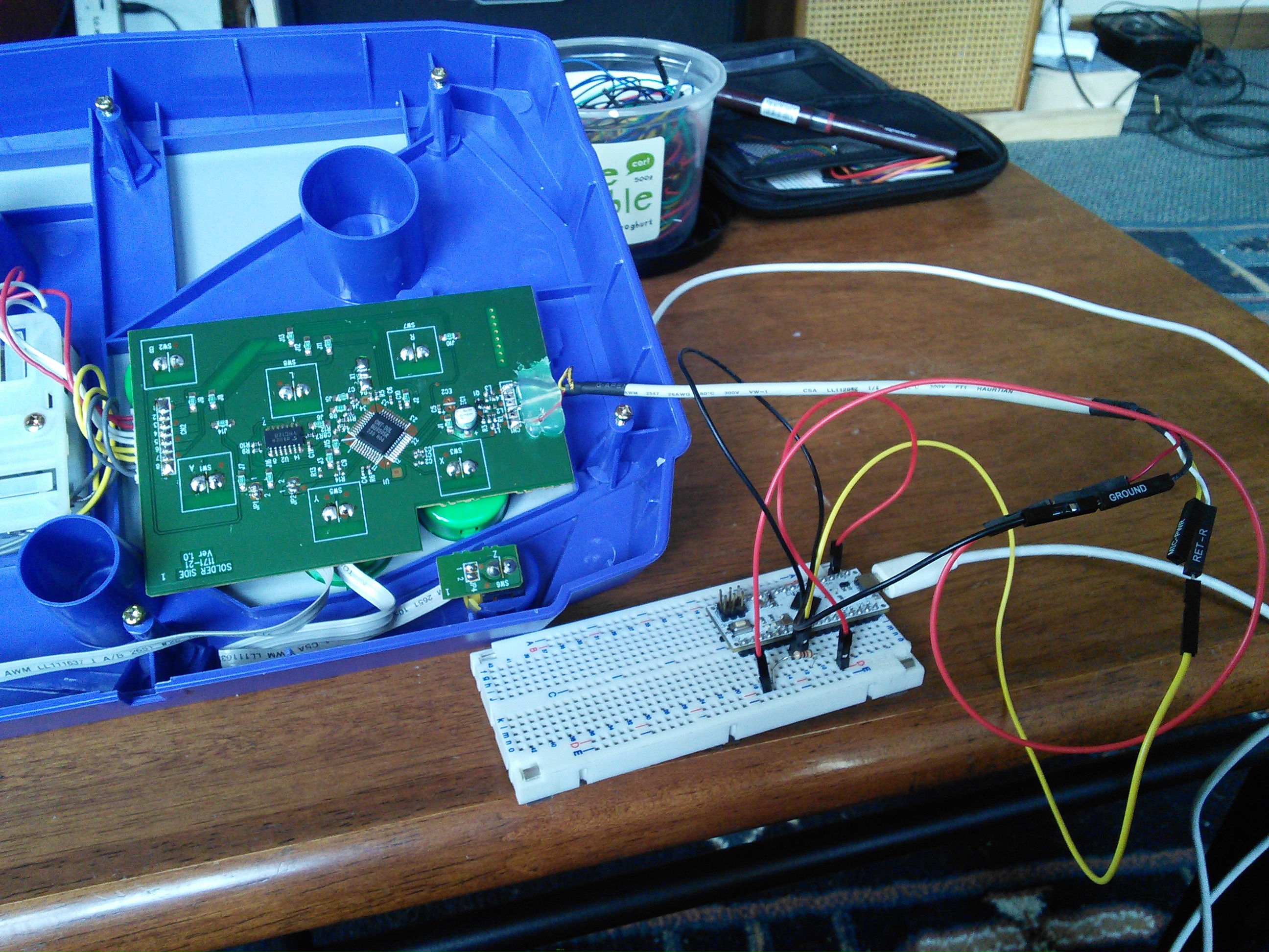
The GameCube arcade stick is actually quite useless for the GameCube itself. It’s missing analog sticks and triggers. However it’s perfect to play Metal Slug on OUYA. It’s using bi-directional serial communication over a single wire. Communication is a bit more involved. Good ressources about the communication protocol are:
- http://www.raphnet.net/electronique/gc_n64_usb/index_en.php
- https://github.com/brownan/Gamecube-N64-Controller
The firmware for this GameCube controller can be found here

Bonus level 1: Composite HID
A popular solution among people building MAME arcade cabinet is to use a device such as the I-PAC to hook-up the arcade controls to the MAME machine. This device cost around US$40. You can make your own by having a single USB-capable AVR handle all the arcade controls. The MCU notifies the host that it will report for multiple HIDs and will communicate a report descriptor for each of the input device. When probing controllers, the host will indicate which one it’s interested in so that the MCU can read the state of the corresponding controller. If running out of AVR digital inputs for the arcade controls one can simply use shift registers or even cheap I2C I/O expanders such as the PCF8574 (less than 1NZ$ on ebay).
A “proof of concept” is available here.
$dmesg
[23159.804203] usb 2-1: New USB device strings: Mfr=1, Product=2, SerialNumber=0
[23159.804211] usb 2-1: Product: Massive arcade sticks
[23159.804219] usb 2-1: Manufacturer: Pete
[23159.811337] input: Pete Massive arcade stick as /devices/pci0000:00/0000:00:1d.0/usb2/2-1/2-1:1.0/input/input16
[23159.811937] hid-generic 0003:03EB:2043.0006: input,hidraw0: USB HID v1.11 Joystick [Pete Massive arcade sticks] on usb-0000:00:1d.0-1/input0
[23159.815344] input: Pete Massive arcade stick as /devices/pci0000:00/0000:00:1d.0/usb2/2-1/2-1:1.1/input/input17
[23159.815877] hid-generic 0003:03EB:2043.0007: input,hidraw1: USB HID v1.11 Joystick [Pete Massive arcade sticks] on usb-0000:00:1d.0-1/input1
$ ll /dev/input/js*
crw-r--r-- 1 root root 13, 0 May 21 16:46 /dev/input/js0
crw-r--r-- 1 root root 13, 1 May 21 16:46 /dev/input/js1
Bonus level 2: Targeting OUYA
Finally if you want to use your gamepad on OUYA, you might want to map one of the button to the middle OUYA button as it is heavily used in the interface.
First step is to gather information about the OUYA controller.
$ sudo apt-get install bluez-compat
[...]

$ sudo hcitool scan
Scanning ...
  B8:5A:F7:C4:13:62 OUYA Game Controller
$ sudo hidd --connect B8:5A:F7:C4:13:62

$ dmesg
[25944.709312] input: OUYA Game Controller as /devices/pci0000:00/0000:00:1d.0/usb2/2-2/2-2:1.0/bluetooth/hci0/hci0:71/input20
[25944.710351] hid-generic 0005:2836:0001.000A: input,hidraw0: BLUETOOTH HID v1.03 Mouse [OUYA Game Controller] on 00:02:5b:92:14:01

$ jstest /dev/input/js0
Driver version is 2.1.0.
Joystick (OUYA Game Controller) has 9 axes (X, Y, Z, Rx, Ry, Rz, (null), (null), (null))
and 19 buttons (BtnX, BtnY, BtnZ, BtnTL, BtnTR, BtnTL2, BtnTR2, BtnSelect, BtnStart, BtnMode, BtnThumbL, BtnThumbR, ?, ?, ?, ?, LeftBtn, RightBtn, MiddleBtn).
Testing ... (interrupt to exit)
Axes:  0:     0  1:     0  2:     0  3:     0  4:     0  5:     0  6:     0  7:     0  8:     0 Buttons:  0:off  1:off  2:off [...]
As we see, the OUYA controller got 19 buttons. When pressing the “OUYA” button, it’s being reported as button number 15. All we have to do now is to update the descriptor to report 19, or even just 15 buttons and set the corresponding bit whenever the choosen physical button is pressed.
blog comments powered by Disqus