The Chilli Power Board
Hola, me dicen Dedoverde
I’m starting growing Bhut Jolokia and other peppers out of seeds. I would like to automate, monitor and document as much as possible the process so that I decided to build an overkill programable power board out of stuff I ordered some time ago from DX as well as some scrap parts. This includes:
- a 4x relay PCB: ~8USD;
- a tiny bluetooth <=> serial module: ~8USD;
- a tiny ATmega328P based prototyping board a.k.a. Arduino pro mini: ~8USD;
- a PCF8583 I2C real time clock: free sample from NXP;
- resitors, crystal, “OR-ing” diodes, buzzer, &c: scrap + Jaycar, less than 10NZD;
- a power board with lots of space inside: free.
For this first milestone, I only want to be able to schedule events like turn heater, lighting or irrigation circuits on & off independantly.
Later I would like to take advantage of the remaining inputs of the embeded MCU to read temperature and humidity
sensors like this one for example.
Bitlash
The power board 8-bit MCU will run an enhanced version of Bitlash. Enhancements include:
- a
timeuser function allowing to set/get the date/time from a real time clock; - a Unix like
cronservice relying on the Bitlash task scheduler: the cron service will check every seconds if cronjobs must be run; - a few user functions used to interact with the cron service:
addcronjob,delcronjob,erasecrontab&lscrontab; - a basic watchdog mechanism which will warn me whem something’s wrong (too many consecutive faulty cronjobs): the watchdog will play the Super Mario tune through the piezo buzzer every minutes in such case.
The code is available on github here.
In the following examples, I’m connected to my power board using screen:
screen /dev/ChilliPowerBoard 57600Switching power plugs
The MCU digital ouputs used to control the power plug relays go from d2 (plug 1) to d5 (plug 4).
For example, in order to switch the third plug on, one would type in the power board shell:
> d4=1In order to toggle the second one:
> d3=!d3This one could be the building block of an Annoy-a-tron:
> d2=random(2)Crontab
The crontab relies on Bitlash task scheduler. It runs once per second:
> ps
0: cronsvc
Toggle the plug #1 every 10 seconds:
> addcronjob(-10,-1,-1,-1,-1,-1,-1,"d2=!d2",0)
> lscrontab
JOB|   s    m    h  dow  dom    M    Y | CMD
 0 |*/10    *    *    *    *    *    * | d2=!d2
Delete cronjob 0:
> lscrontab
JOB|   s    m    h  dow  dom    M    Y | CMD
 0 |*/10    *    *    *    *    *    * | d2=!d2
> delcronjob(0)
> lscrontab
JOB|   s    m    h  dow  dom    M    Y | CMD
From monday to friday, Switch on plug #2 from 8am to 11:30am:
> addcronjob(0,0,8,0b01111100,-1,-1,-1,"d3=1",0)
> addcronjob(0,30,11,0b01111100,-1,-1,-1,"d3=0",1)
> lscrontab
JOB|   s    m    h  dow  dom    M    Y | CMD
 0 |   0    0    8   7C    *    *    * | d3=1
 1 |   0   30   11   7C    *    *    * | d3=0
Erase the crontab:
> erasecrontabEEPROM
All the cronjobs are stored in the MCU’s’ EEPROM so that the number of job is limited.
Since Bitlash is also using the EEPROM to store functions, we need to tell it at compile time how much of
it can be used (see the “Reserving EEPROM for Other Applications” section in the Bitlash User’s Guide).
Dump of the EEPROM:
> peep

E000:  cron svc$   cro nd;   $sta rtcr  ond$  cro  nd;  run   cron svc,  1000 ; $p  lug$ $...
E040:  .... ....  .... ....  .... ....  .... ....  .... ....  .... ....  .... ....  .... ....
E080:  .... ....  .... ....  .... ....  .... ....  .... ....  .... ....  .... ....  .... ....
E0C0:  .... ....  .... ....  .... ....  .... ....  .... ....  .... ....  .... ....  .... ....
E100:  .... ....  .... ....  .... ....  .... ....  .... ....  .... ....  .... ....  .... ....
E140:  .... ....  .... ....  .... ....  .... ....  .... ....  .... ....  .... ....  .... ....
E180:  .... ....  .... ....  .... ....  .... ....  .... ....  .... ....  .... ....  .... ....
E1C0:  .... ....  .... ....  .... ....  .... ....  .... ....  .... ....  .... ....  .... ....
E200:  .... ....  .... ....  .... ....  .... ....  .... ....  .... ....  .... ....  .... ....
E240:  .... ....  .... ....  .... ....  .... ....  .... ....  .... ....  .... ....  .... ....
E280:  .... ....  .... ....  .... ....  .... ....  .... ....  .... ....  .... ....  .... ....
E2C0:  .... ....  .... ....  .... ....  .... ....  .... ....  .... ....  .... ....  .... ....
E300:  .... ....  .... ....  .... ....  .... ....  .... ....  .... ....  .... ....  .... ....
E340:  .... ....  .... ....  .... ....  .... ....  .... ....  .... ....  .... ...�  .... ..d2
E380:  =!d2 $$$$  ���� ����  ���� ����  ���� ����  ���� ����  ���� ����  ���� ����  ���� ����
E3C0:  ���� ����  ���� ����  ���� ����  ���� ����  ���� ����  ���� ����  ���� ����  ���� ���.
Bluetooth setup (Pimp my HC06)
First thing I’m going to do, is setup the BT module.
According to the product datasheet (chapter 9 “AT command set”), one can change the name, the baudrate as well as the pin of the module sending
AT commands on its serial interface.
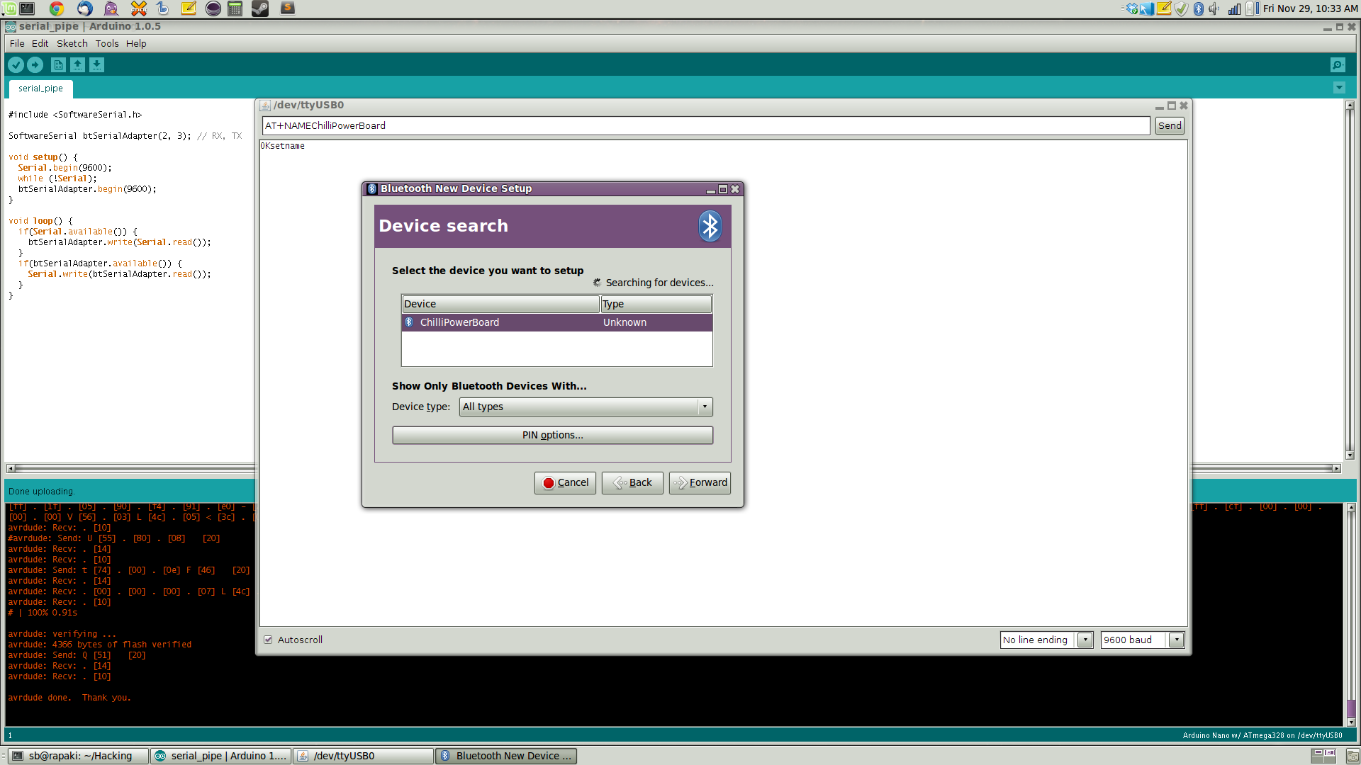
In order to do so, I will use an Arduino nano connected to my computer and loaded with a serial pipe program.
Then, I will just send the correct AT commands from a serial terminal.
I’m using the “serial monitor” built into the Arduino IDE but one could use gtkterm or even screen.
The pipe program:
 1 #include <SoftwareSerial.h>
 2
 3 SoftwareSerial btSerialAdapter(2, 3); // RX, TX
 4
 5 void setup() {
 6   Serial.begin(9600);
 7   while (!Serial);
 8   btSerialAdapter.begin(9600);
 9 }
10
11 void loop() {
12   if(Serial.available()) {
13     btSerialAdapter.write(Serial.read());
14   }
15   if(btSerialAdapter.available()) {
16     Serial.write(btSerialAdapter.read());
17   }
18 }
and the circuit:
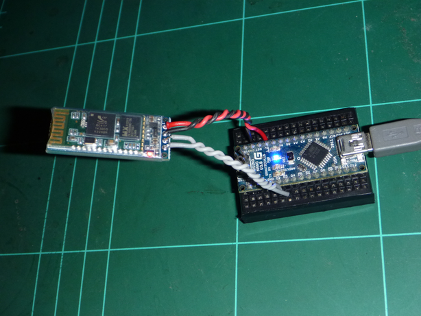
We’re ready to send the AT commands:


Linux setup
Let’s go through the few steps needed to easily talk to the power board from Linux.
- First thing is to retrieve the device address:
1 $ hcitool scan
2 Scanning ...
3 00:12:10:23:02:31 ChilliPowerBoard- Then we can add some stuff in
/etc/bluetooth/rfcomm.confto connect auto-magically at startup:
 1 #
 2 # RFCOMM configuration file.
 3 #
 4
 5 rfcomm0 {
 6         # Automatically bind the device at startup
 7         bind yes;
 8
 9         # Bluetooth address of the device
10         device 00:12:10:23:02:31;
11
12         # RFCOMM channel for the connection
13         channel 1;
14
15         # Description of the connection
16         comment "Chilli Power Board";
17 }- Then we setup permission on the
/dev/rfcomm0file and tell modem-manager not to probe the power board. In/etc/udev/rules.d/100-ChilliPowerBoard.rules(create this one):
KERNEL=="rfcomm0", MODE="0666", ENV{ID_MM_DEVICE_IGNORE}="1"- Add ourselves to the
dialupgroup (or whatever group is used for rfcomm on your distrib). In/etc/group:
dialout:x:20:sb- Optionally create a user friendly symlink:
$ sudo ln -s /dev/rfcomm0 /dev/ChilliPowerBoard- Manualy connect to the power board ?
1 $ sudo rfcomm connect 0
2 Connected /dev/rfcomm0 to 00:12:10:23:02:31 on channel 1
3 Press CTRL-C for hangup- Disconnect …
$ sudo rfcomm release 0- Talk to the board:
$ screen /dev/ChilliPowerBoard 57600- Optionally create a user friendly alias:
$ alias ChilliPowerBoard="screen /dev/ChilliPowerBoard 57600"That’s all ! The BT module is now ready and I will keep it on a corner of my desk until it’s time to put everything together. The next stage is to hack a little RTC circuit.
Real Time Clock
Since I’m willing to schedule events at a given date and time on my power board, it needs to track time pretty accurately.
### Basic circuit
I had a spare PCF8583 I2C real time clock I decided to use:

All it needs is a 32.768Khz crystal (\(2^{15}\) cycles per seconds).
The basic circuit looks like this:
According to another datasheet, page 10 of 52, the theoretical capacitance required at OSCI is 18pF. The corresponding capacitor should be connected to \(V_{DD}\) (page 11 of 52). I added one to the circuit in the end.
I choosed not to use a trimpot capacitor \(C_{trim}\) (5 to 25pF as per datasheet) since I can easily compensate for the expected 5 minutes error a year
by resetting the RTC via bluetooth, based on NTP time for example (see page 24).
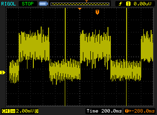
Also, page 12 of 37, it is said that
> If the alarm enable bit of the control and status register is reset (logic 0), a 1 Hz signal is observed on the interrupt pin \(\overline{INT}\).
and page 13: > In the clock mode, if the alarm enable is not activated (alarm enable bit of the control and > status register is logic 0), the interrupt output toggles at 1 Hz with a 50 % duty cycle (may > be used for calibration).
Here is what I observe (looks good to me):
Power backup
RTC circuits often come with a backup power. For example a 3V coin battery.
A simple way to implement this is a diode based “OR-ing” circuit.
Here is a little schematic and an attempt at explaining how it works (I hope you can read my handwriting):
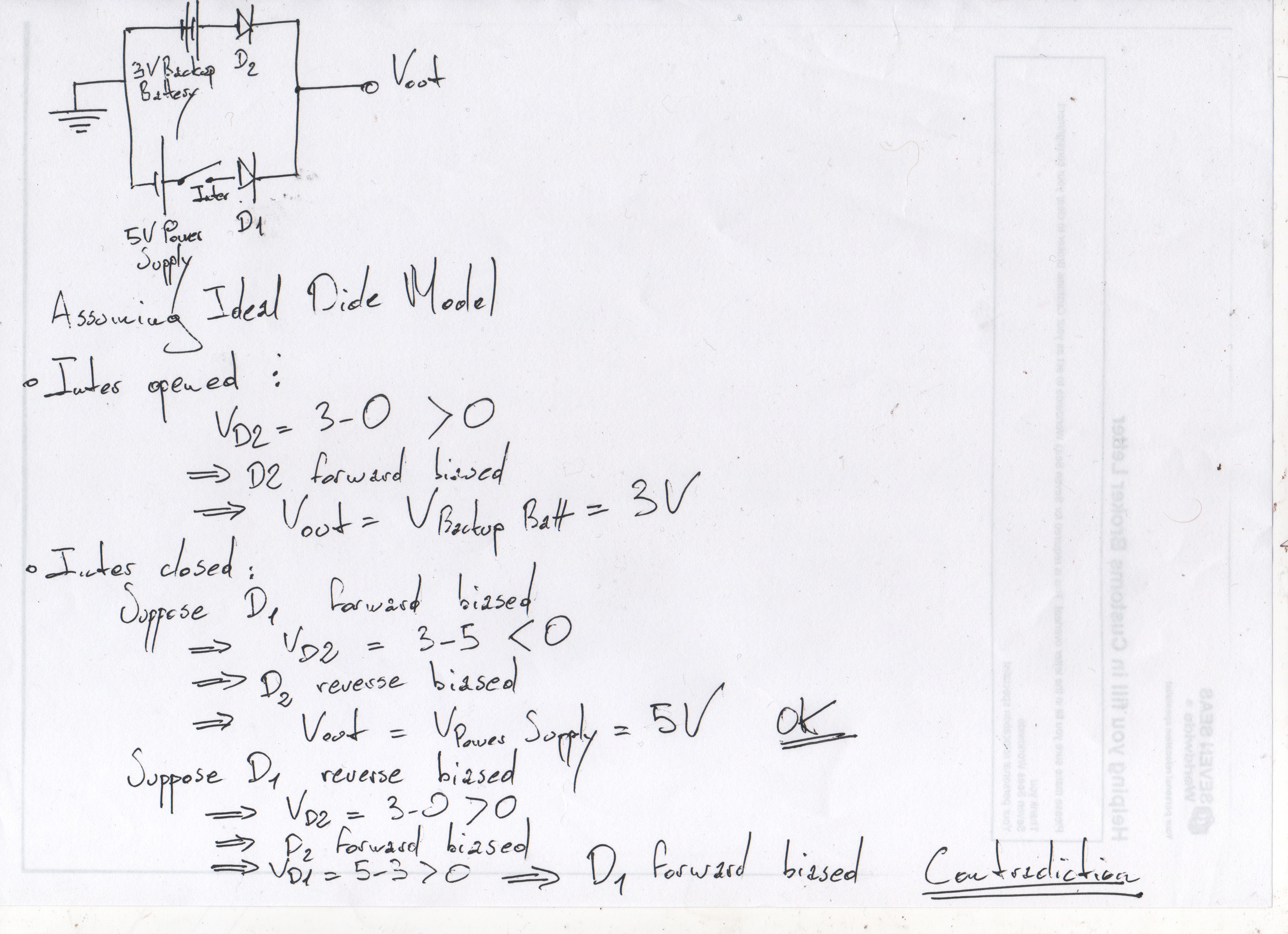
The circuit upgraded with a backup power:
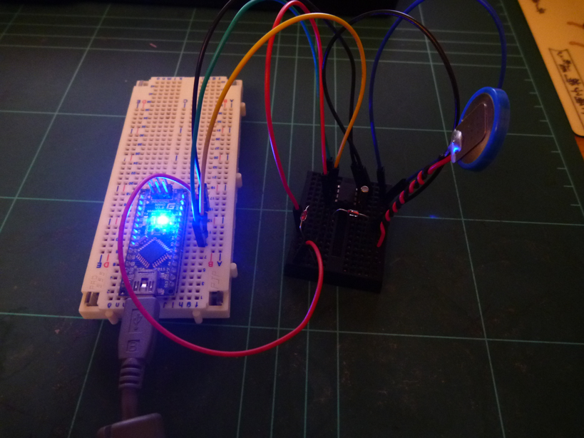
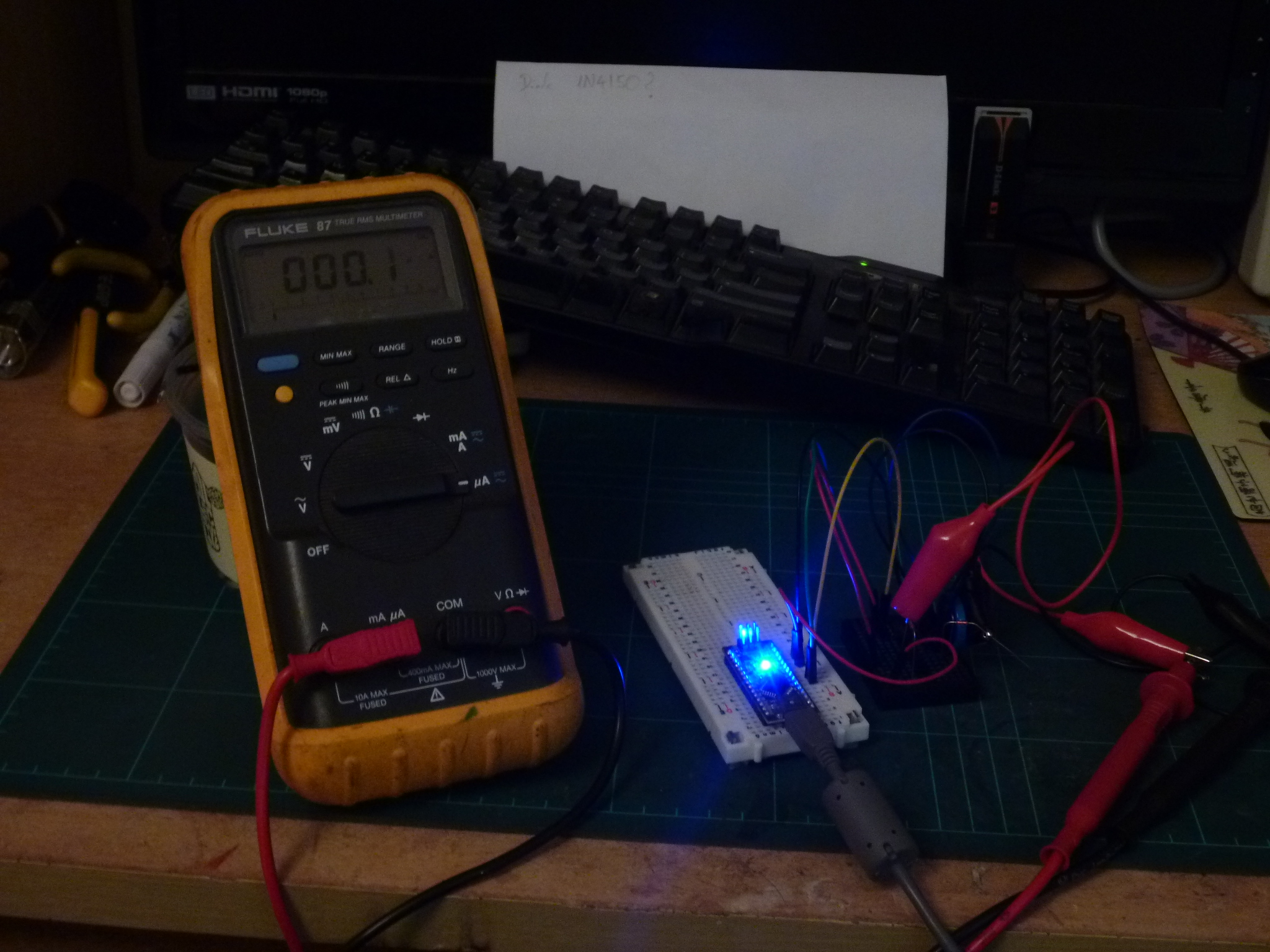
I only had 1N4150 diodes available. Best practice for this circuit is to use Schottky diode in order to minimise the forward voltage drop.
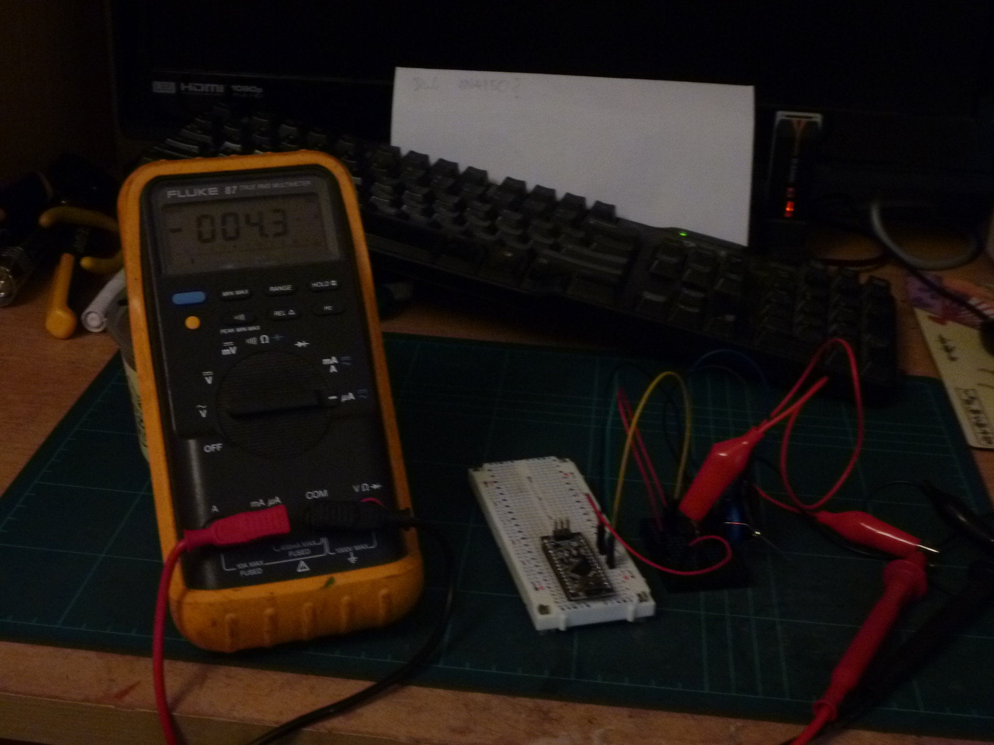
I measured the current with and without primary power supplied and checked against the datasheet (page 21). The measured current is higher than what’s expected (4.3 vs ~3 micro amps @ 3V). I wonder why.

Since the circuit is simple, I decided to transfer it on a stripboard:
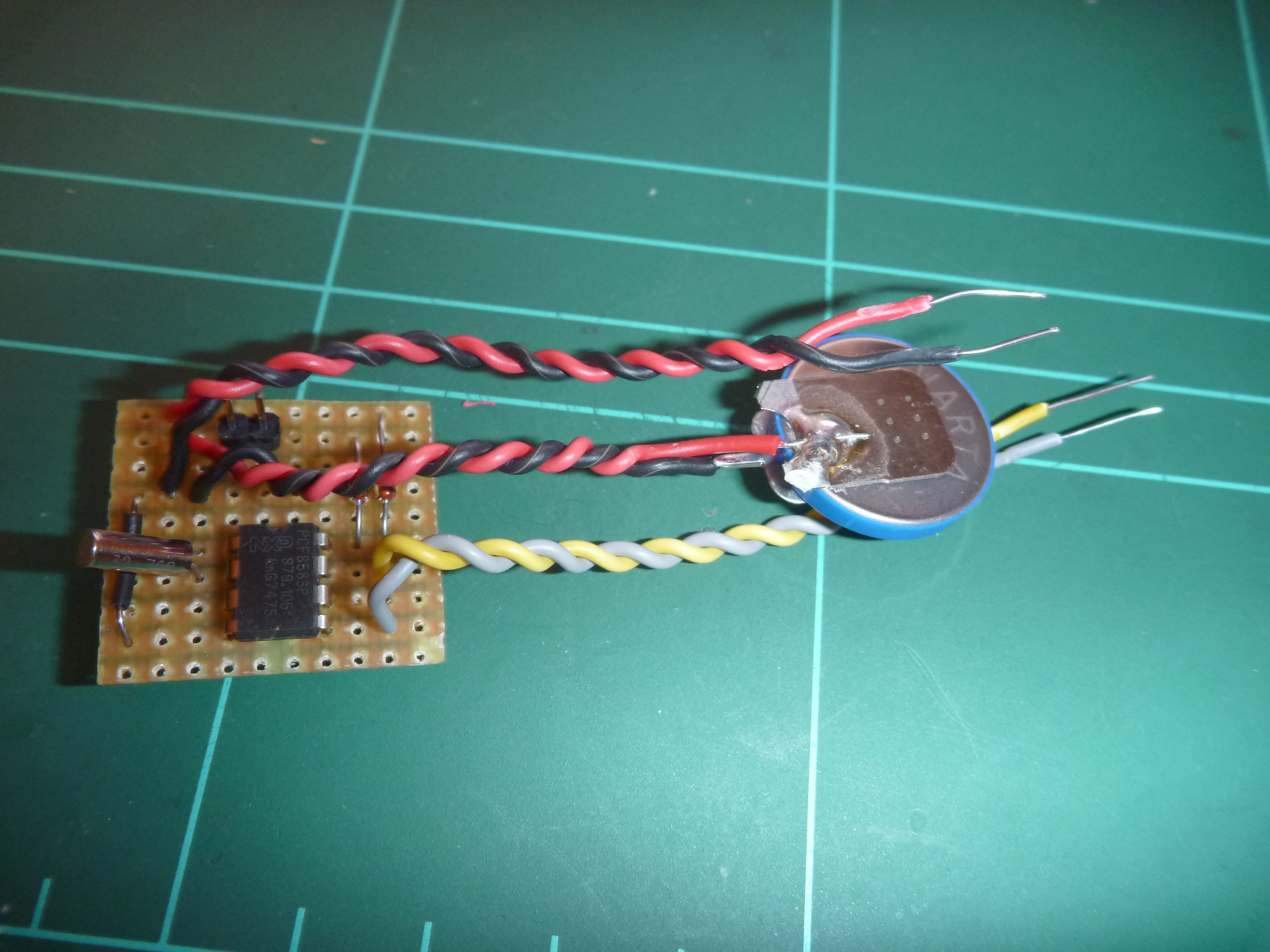
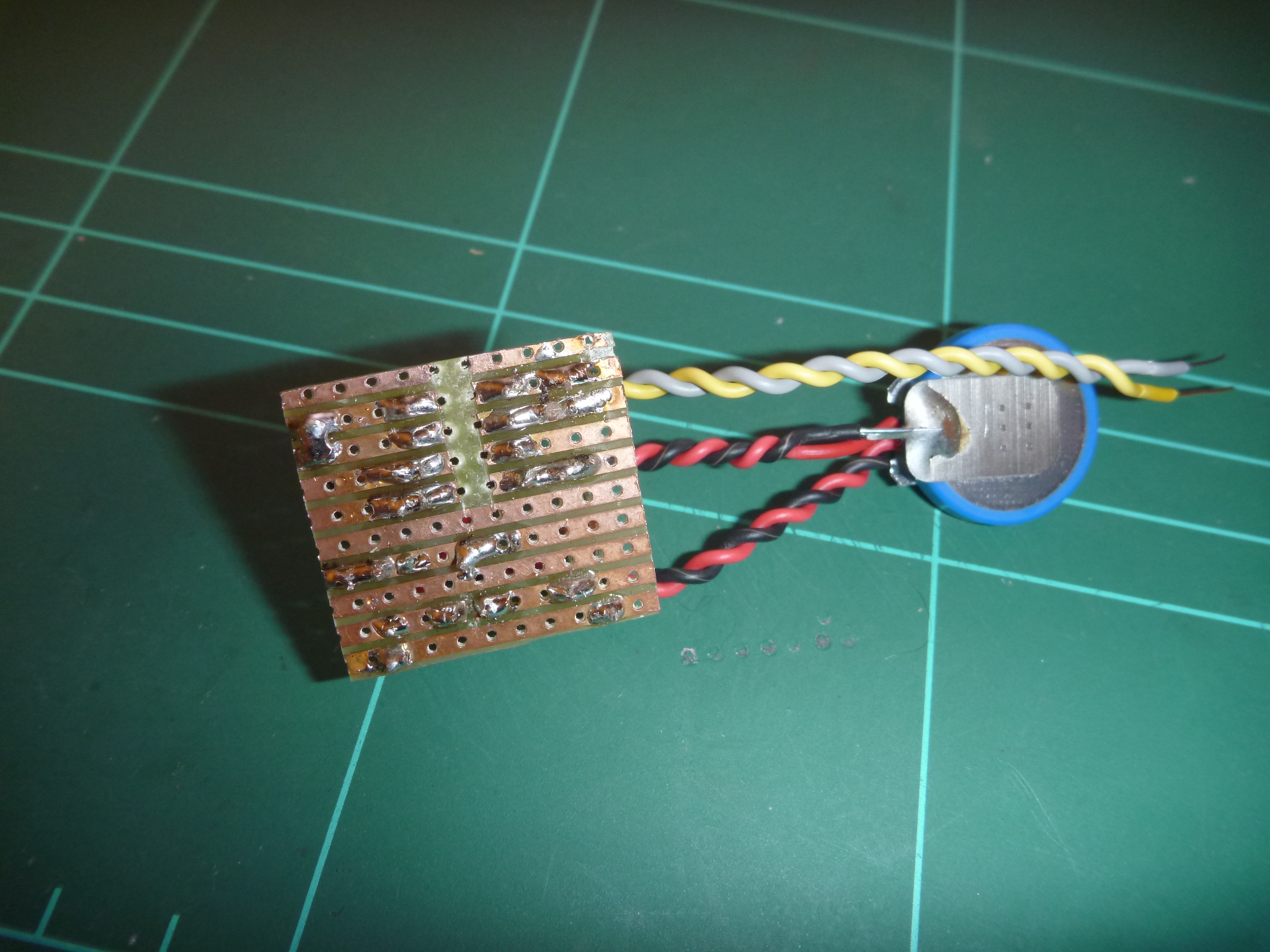
This wasn’t a great idea. The clock is either running too fast or too slow. Just like this guy.
Hopefuly the UM10301 datasheet, section “14. PCB layout guidelines” will allow me
to create a proper PCB. But that will be another time.
Also it’s worth noting that a DX RTC module costs about 3 yankee dollars.
That’s all for the RTC hardware. Let’s talk quickly about the software.
Software
On the software side, a PCF8583 Arduino library is available on github:
- it’s incomplete because I found out that a dude called jiki974 added support for the daily alarm but these changes never made it to the repo;
- it’s somehow buggy since it ignores the day of the week and doesn’t really cope well with leap years.
Anyway, I submitted a pull request to cope with these issues.
Interacting with the component is done via read and write operations from and to its CMOS RAM.
The map of the RAM is at available page 8 of the datasheet.
Ultimately this is what a time command using the PCF8583 library looks like in Bitlash:
 1 numvar time() {
 2     if(getarg(0) == 0) {
 3       static const char* DayStrings[] = {
 4         "Sunday", "Monday", "Tuesday",
 5         "Wednesday", "Thursday", "Friday",
 6         "Saturday"};
 7       theRTClock.get_time();
 8       char t[50];
 9       sprintf_P(t, PSTR(" %04d/%02d/%02d %02d:%02d:%02d"),
10         theRTClock.year, theRTClock.month, theRTClock.day,
11         theRTClock.hour, theRTClock.minute, theRTClock.second);
12       sp(DayStrings[theRTClock.get_day_of_week()]); sp(t); speol();
13     } else if(getarg(0) == 6) {
14        theRTClock.year= getarg(1);
15        theRTClock.month = getarg(2);
16        theRTClock.day = getarg(3);
17        theRTClock.hour = getarg(4);
18        theRTClock.minute = getarg(5);
19        theRTClock.second = getarg(6);
20        theRTClock.set_time();
21     }
22    return 0;
23 }
Flashing the MCU
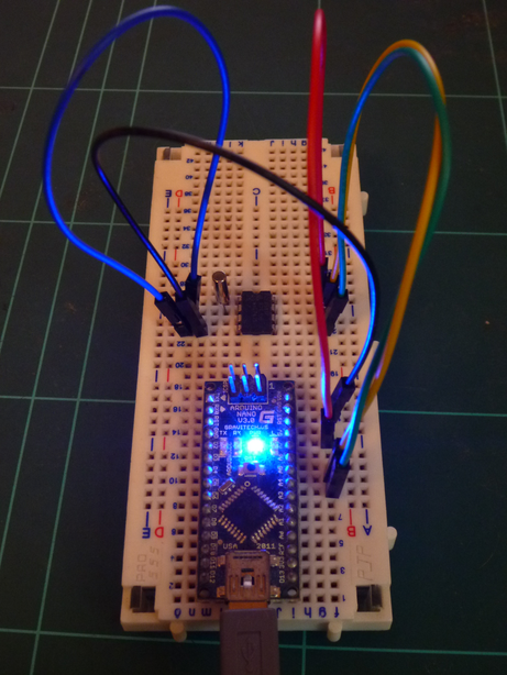
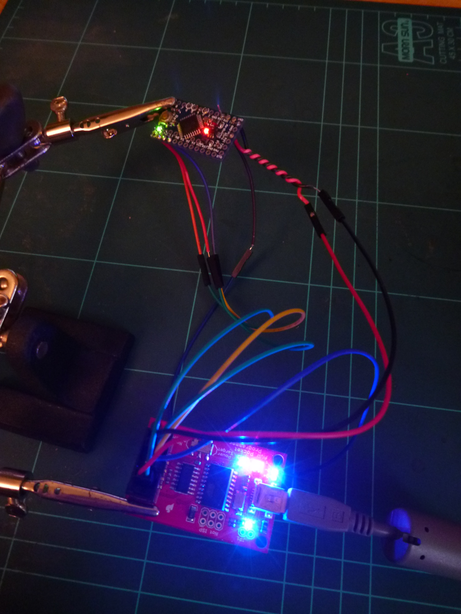
I’m programming the MCU using a USBtinyISP clone, bypassing the bootloader. I find this method really reliable and it allows me to play with the fuse bits as well.
It looks like this:
On my Linux distribution, I setup credentials for the USBtinyISP by creating a /etc/udev/rules.d/103-USBtinyISP.rules file containing:
SUBSYSTEM=="usb", ATTR{idVendor}=="1781", ATTR{idProduct}=="0c9f", GROUP="plugdev", MODE="0666"I must tell the Arduino IDE I’m using an ISP programmer: File => Upload Using Programmer or Ctrl+Shift+U,
as well as select the proper programmer in Tools => Programmer.
I could also use avrdude directly:
$ avrdude -v -c usbtiny -p m328p -U flash:w:ChilliPowerBoard.hexPutting everything together
- Software: check !
- BT <=> serial pimping: check !
- DIY RTC: check ! (kinda)
- Flashed MCU: check !
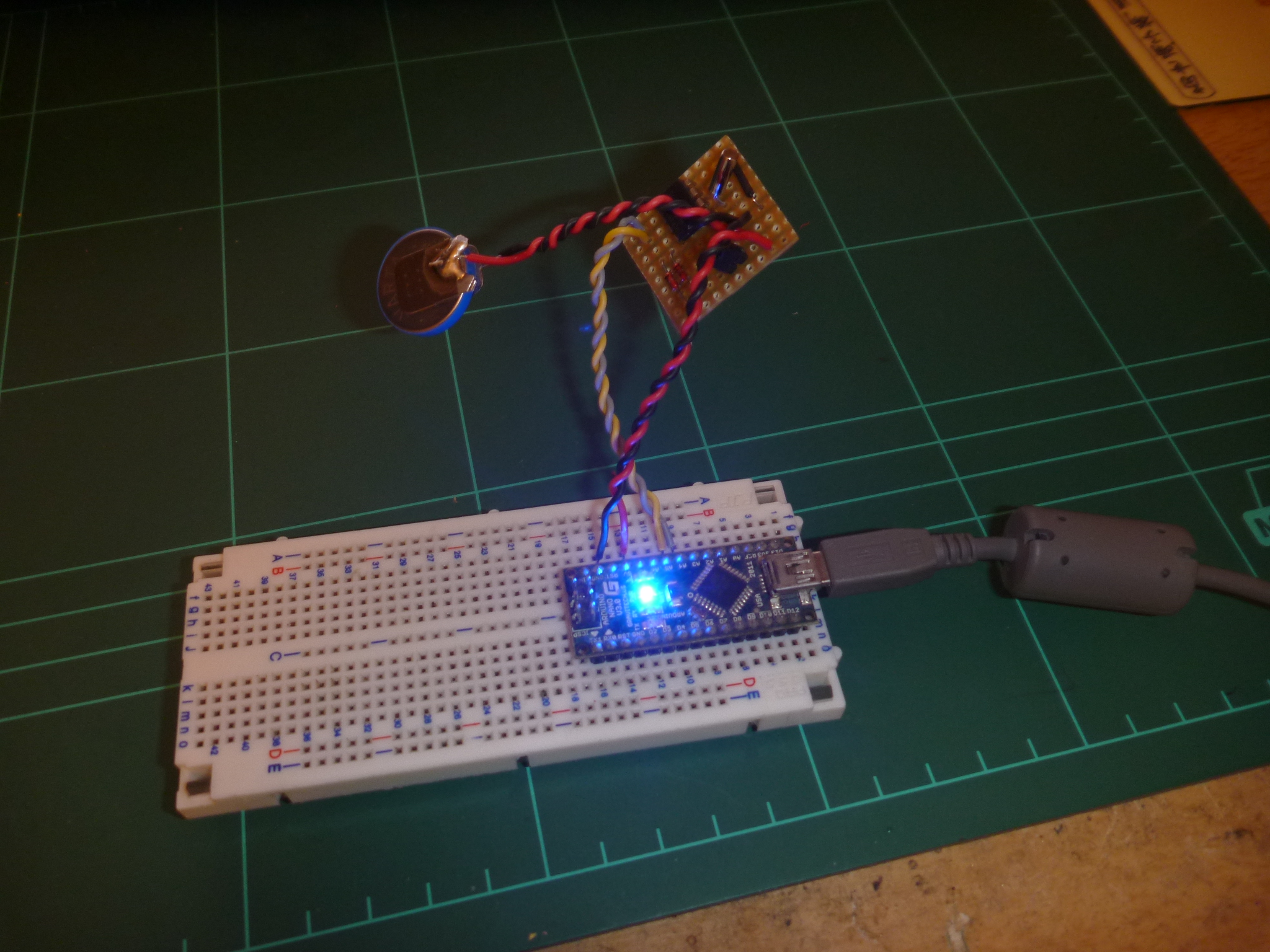
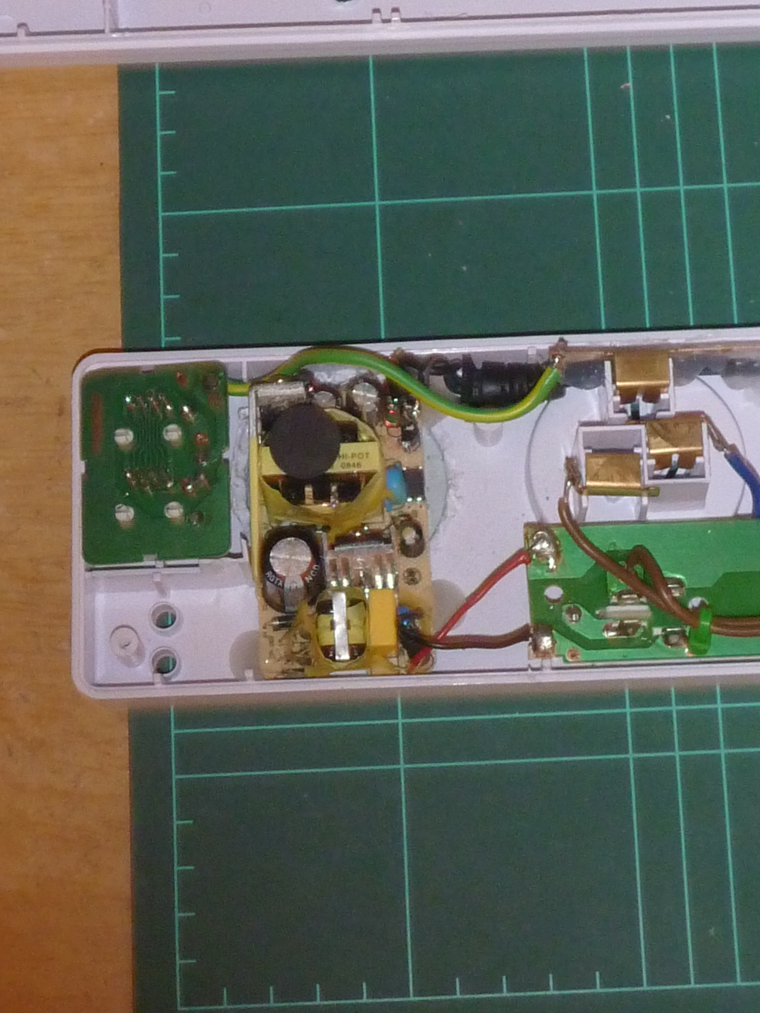
We’re good to go. Here is the plan:
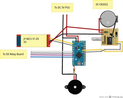
Its implementation looks like this:
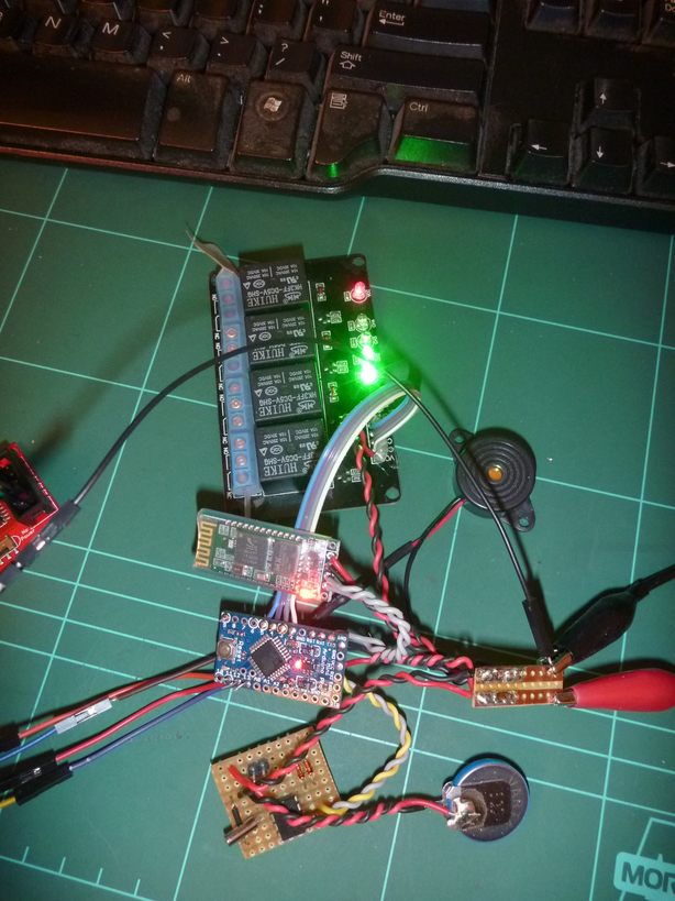
Now comes the real challenge: fit everything in the power board …
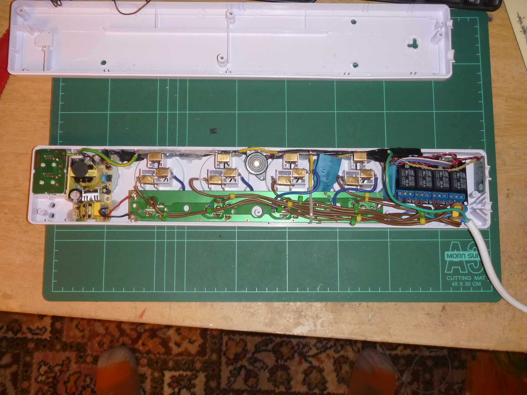
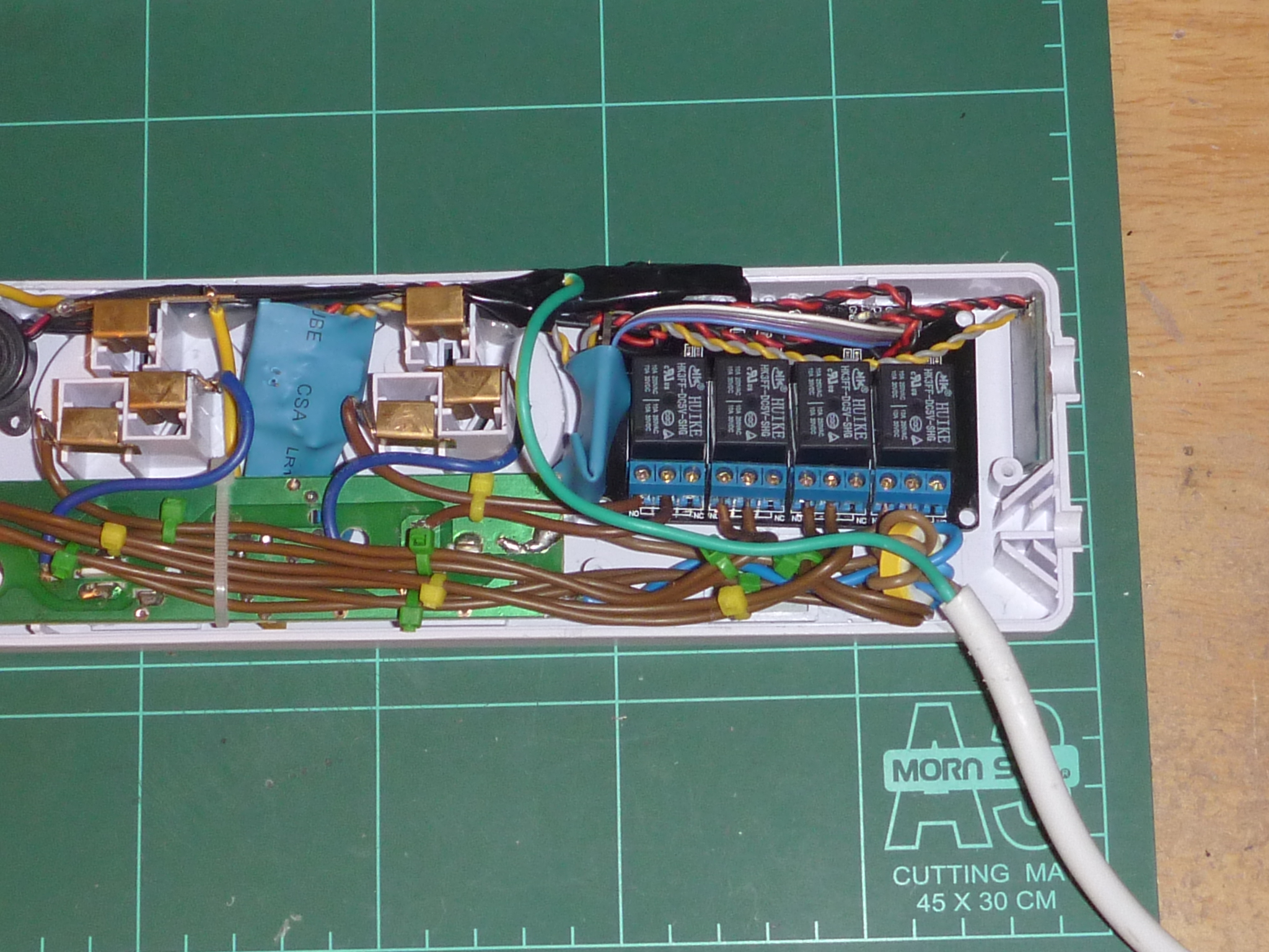
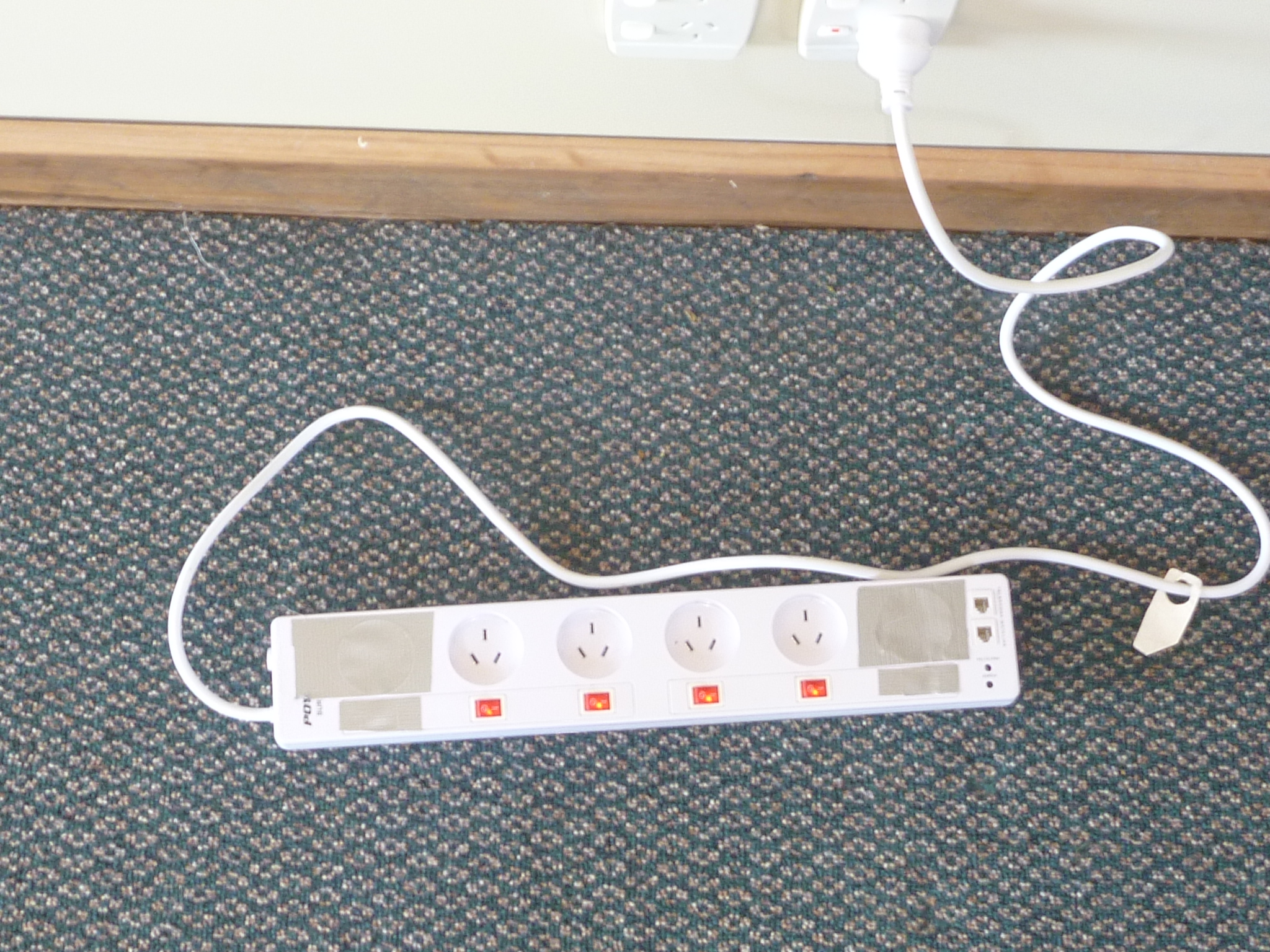
Conclusion
It’s a bit scarry and looks like a dangerous protoype. It works just fine. In the near futur I plan to design a proper RTC circuit, hack an Android app to control the board and ultimately read temperature and humidity sensors. That’s all folks.
blog comments powered by Disqus